 Static Analysis of Five Story Moment Resistant Steel Frame
 Static Analysis of Five Story Moment Resistant Steel Frame
[ Problem Description ]
[ Input and Output Files ]
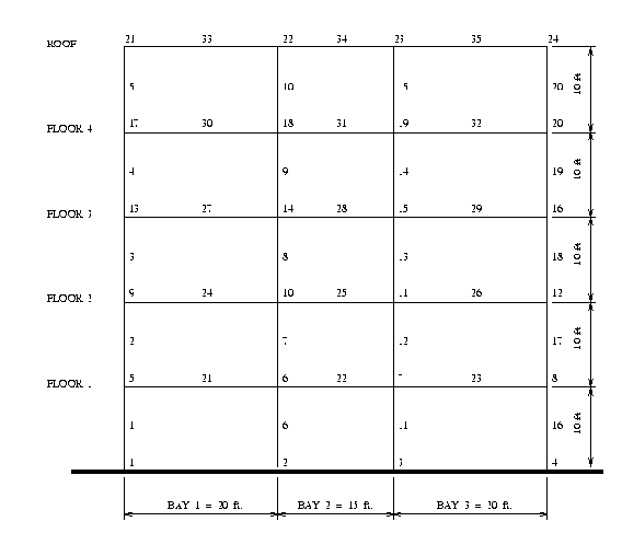
We begin with a linear static analysis of a five story steel moment resistant frame with dimensions and preliminary section sizes as shown in Figure 1.

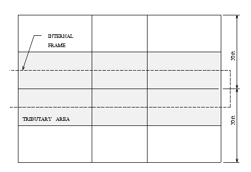
We will assume that this frame is one row of frames spaced at 20 ft centers, as shown in Figure 2.

The frame is constructed with two steel section types, and one material type. The columns are of type UC 12 X 12, with Izz = 1541.9in^4, Iyy = 486.3in^4, and a cross section area 47.38in^2. The beams are of section type UB 21 X 81/4, with Izz = 1600.3in^4, Iyy = 66.2in^4, and cross section area 21.46in^2. The beams and columns have Youngs Modulus 29000ksi, and yield stress 36.0 ksi.
The frame will be analysed for gravity loads plus a moderate lateral earthquake load. Wind and other loads are omitter for simplicity. The specified dead load is 80 lbf/ft^2, and the specified live load 40 lbf/ft^2 for the four floors, and 20 lbf/ft^2 for the roof. We will assume that the tributary area for gravity loads is rectangular in shape, with a uniform load distribution along each girder span of the frame. With the frames spaced 20 ft apart, it follows that the gravity loads are 0.200 kips/in, and 0.1667 kip/in on the roof. Total gravity loads are 663800 lbf.
In this first release of ALADDIN, external loads may only be applied to the nodes. Consequently, formulae for the fixed end moments due to gravity loads must be explicity included in the data file. If the loading per unit length is w, and L is the span length of the frame bay, then the fixed end shear force is wL/2, and the fixed end moment is wL^2/12.

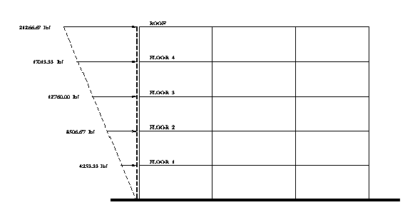
Moderate earthquake ground motions are modeled with a psuedo-static lateral force equal to 10% of total gravity loads. The lateral forces are distributed over the height of the frame as shown in figure 3.
We will assume full fixity for the bases of the columns. Each node of the building frame will be modeled with two translational and one rotational degree of freedom. Axial forces in the beam elements are removed by lumping the horizontal degrees of freedom at each floor level. Together these assumptions imply 5 displacement and 4 rotational degrees of freedom per floor level, leading to (45 X 45) global stiffness matrix.