Ensure that the manipulator is correctly connected to the AC100 controller.
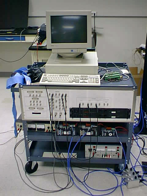
The manipulator is controlled using the AC100 rapid prototyping system. This system was assembled by George Kantor. Additional information about the AC100 system can be found in his master's thesis from 1995 or from the Integrated Systems documentation in the ISL. The manipulator is connected to the controller via the I/O connectors on the AC100 system cart (shown below).
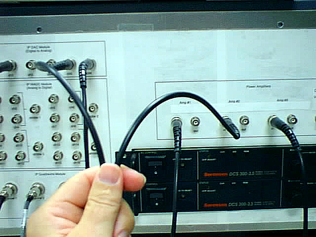
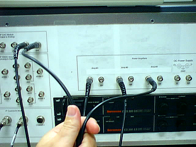
The signal to the motor amps come from IP DAC (digital to analog) Module on the AC100 cart. At the time of this writing only channels 2,4, and 6 are operating properly. So, the code that has been written for the manipulator, and that is left to demonstrate the manipulator are configured such that channel 2 drives leg 1, channel 5 drives leg 2, and channel 6 drives leg 3. The connections made by BNC cable from the DAC module to the amps are shown in the three following photos.

The cables from the encoders are connected to the control cart with 7-pin connectors to the IP Quadrautre Module channels 1, 2, and 3 as shown in the next photo.
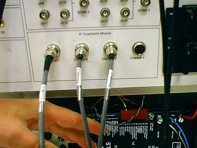
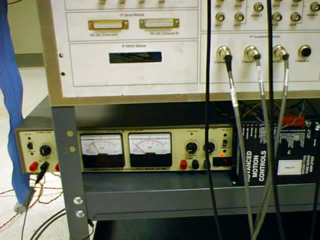
The user should also note that the power for the encoders is not supplied by the IP Quadrautre Module, as one might expect. Behind the panel, the power is actually supplied by the power supply located just below the IP Quadrautre Module as shown in the next photo. So, it's important that this power supply is turned on.
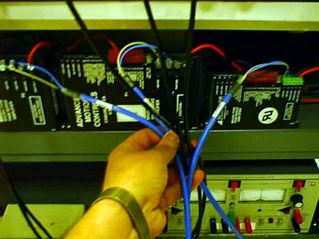
The connections made between the motor amps are shown in the next photo. The clear wire is connected to the "- Motor", the blue wire is connected to the "+ Motor", and the black wire is connected to the power ground for each motor.
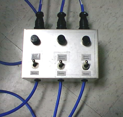
A box was also fabricated for the user to hold during the manipulator operation, that provides a quick motor disenable/enable switch and a fuse. The connections to this box are shown in the next photo.