 Nonlinear Analysis of Cantilever
 Nonlinear Analysis of Cantilever
[ Problem Description ]
[ Finite Element Analyses ]
[ Input File ]
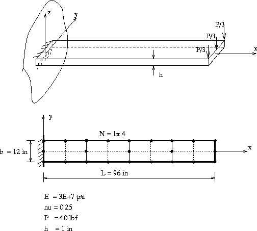
A cantilever beam with rectangular cross section is subjected to a concentrated load at the tip of the cantilever.

The length of the cantilever L is 10 in, width is 1 in and thickness is 1 in.
The initial load in z direction is P = -300 lbf.
Again two cases are studied. Four through-thickness integration points are used in both cases.
Case 1 : In the first case, the material is a Bi-Linear stress-strain curve with isotropic hardening. The Young`s modulus is E = 2.9E+7 psi, Possion ratio is 0.2, Et = 0.1 E and the yield stress is 36 ksi. The load steps are illustrated in Figure 1, and the results for the hysteresis loop is given in Figure 2.


Case 2 : In the second case, the material model is a Ramberg-Osgood stress-strain curve with isotropic hardening. The young's modulus is E = 2.9E+7 psi, Possion ratio is 0.2, the Ramberg-Osgood coefficient is alpha = 3/7, the strain hardening exponent is n = 6. The yield stress is 36 ksi.
The load steps are illustrated in Figure 3, and the results for the hysteresis loop are given in Figure 4.

