 Structural Analysis of Three-Span Beam Structure
 Structural Analysis of Three-Span Beam Structure
[ Problem Statement ]
[ Finite Element Mesh ]
[ Equivalent Fixed End Reactions ]
[ Displacements ]
[ Member Forces ]
[ Support Reactions ]
[ Input/Output Files ]
You will need Aladdin 2.0 to run this problem.
In this example we will compute the joint displacements, distribution of bending moments and shear forces, and support reactions for the three-span beam structure shown in Figure 1.

The total width of the beam is 25 m. It is constructed from steel sections having moment of inertia I = 6.6 x 10^8 mm^4 and cross section area A = 4.26 x 10^4 mm^2. The steel material has modulus of elasticity E = 200 GPa.
The structure carries three external loads -- a 10 kN point load in the middle of span 1, a uniform load of 2 kN/m across span 2, and a point load of 10 kN point at the tip of span 3.
Solution Procedure
This problem is complicated by the distributed loadings along the beam structure, and the limitation that Aladdin 2 does not explicitly support distributed element loads as a special type of input.
This does not mean that problems involving element loads cannot be handled by Aladdin, however. All that is required is a conversion of the element loads to equivalent nodal loads, followed by the appropriate matrix manipulations.
The step-by-step solution procedure is:
The fixed-end reactions calculated at Step 2 should be mapped to the global d.o.f. and added to the external loads applied directly to the joints. In other words, we have:
[ K ] [ x ] = [ F_r ] + [ F_j ]
where
    [  K  ] = Global stiffness matrix.
    [  x  ] = Vector of joint displacements.
    [ F_r ] = Vector of reactions caused by distributed
              element level forces.
    [ F_j ] = Vector of external loads applied directly
              to the beam structure joints (e.g, see "D").
[ K ] [ x ] = [ F_r ] + [ F_j ]
for the joint displacements.
[ f_e ] = [ k_e] [ x_e ].
[ f_c ] = [ f_e ] - [ f_r ].
where
[ f_r ] = element level reactions computed at Step 2.
Finite Element Mesh
The beam structure will be modeled with three beam column elements, as labeled in Figure 2.

The finite element nodes are generated with:
    node = 1;
    AddNode(node, [  0 m, 0 m ] );
    node = 2;
    AddNode(node, [ 10 m, 0 m ] );
    node = 3;
    AddNode(node, [ 20 m, 0 m ] );
    node = 4;
    AddNode(node, [ 25 m, 0 m ] );
Three finite elements are attached to the nodes with:
    elmtno = 1;
    AddElmt( elmtno, [ 1, 2 ], "beamelmt");
    elmtno = 2;
    AddElmt( elmtno, [ 2, 3 ], "beamelmt");
    elmtno = 3;
    AddElmt( elmtno, [ 3, 4 ], "beamelmt");
Section and Material Properties
We assume that the entire beam structure is contstructed from one section type and one material labeled "beamelmt".
    ElementAttr("beamelmt") { type     = "FRAME_2D";
                              section  = "beamsection";
                              material = "beammaterial";
                            }

    SectionAttr("beamsection") { Izz    = 6.60e8 mm^4;
                                 area   = 4.26e4 mm^2;
                               }

    MaterialAttr("beammaterial") { poisson = 0.25;
                                   E       = 200 GPa;
                                 }
FRAME_2D is the name of our two-dimensional beam column element.
Boundary Conditions
We assume that the left hand support has full-fixity, and that the two internal supports are full-fixed in the vertical direction. The latter may freely displace in the horizontal and rotational directions, however.
The block of code:
    nodeno = 1;
    FixNode( nodeno, [ 1, 1, 1 ]);
    nodeno = 2;
    FixNode( nodeno, [ 0, 1, 0 ]);
    nodeno = 3;
    FixNode( nodeno, [ 0, 1, 0 ]);
establishes the required boundard conditions.
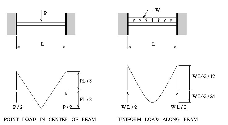
Figure 3 shows the fixed end reactions and distributions of bending moment for the two types of external loading shown in Figure 1.

Since the fixed-end reactions are needed at both Steps 3 and 6 of the solution procedure, a convenient way of saving the element level reactions is with the array:
    forces = Matrix( [3,6] );
    forces = ColumnUnits ( forces, [ N, N, N*m, N, N, N*m ]);
The i-th row of array forces stores the fixed end reactions for the i-th element. For example, the fixed end reactions and moments for element 2 are given by:
    L = 10 m; W = 2 kN/m;

    forces[2][2] = -W*L/2;
    forces[2][3] = -W*L*L/12;
    forces[2][5] = -W*L/2;
    forces[2][6] =  W*L*L/12;
Similar expressions are written for elements 1 and 3.
We will assume that the structure is linear elastic and that "small deflection theory" holds -- that is, the joint displacements are very small compared to the dimensions of the structure, and that equilibrium of the deformed structure can be expressed in terms of the undeformed coordinate system (of course this is is an approximation).
The global stiffness matrix and external load vector are formed by the statement pair:
    eload = ExternalLoad();
    stiff = Stiff();
The global displacements are computed and printed with:
    displ = Solve(stiff, eload);
    PrintDispl(displ);
The program output is:
    ============================================================
     Node                           Displacement
       No            displ-x           displ-y             rot-z
    ============================================================
     units                m                 m               rad
       1         0.00000e+00       0.00000e+00       0.00000e+00
       2         0.00000e+00       0.00000e+00       1.35281e-04
       3         0.00000e+00       0.00000e+00      -6.98954e-04
       4         0.00000e+00      -6.65133e-03      -1.64592e-03
From Steps 5 and 6 in our solution procedure it is evident that the correct element level member forces are given by:
[ f_c ] = [ k_e] [ x_e ] - [ f_r ].
In the case of the FRAME_2D element the element nodal loads corresponding to
[ k_e] [ x_e ]
can be retrieved from the finite element library with the function call (note, not all elements have this property):
elmt = GetStress( [ii], displ );
Here, "ii" is the element number, "displ" is the vector of global joint displacements and "elmt" is a 2 x 5 matrix containing the element coordinates and the member forces acting at the joints.
Therefore, the block of code:
    for ( ii = 1; ii <= 3; ii = ii + 1 ) {
       print "\nMember forces for Element", ii, "\n\n";
       elmt = GetStress( [ii], displ );

       print "End 1 : Horizontal =", elmt[1][3] - forces [ ii ][1] ,"\n";
       print "        Vertical   =", elmt[1][4] - forces [ ii ][2] ,"\n";
       print "        Moment     =", elmt[1][5] - forces [ ii ][3] ,"\n";
       print "End 2 : Horizontal =", elmt[2][3] - forces [ ii ][4] ,"\n";
       print "        Vertical   =", elmt[2][4] - forces [ ii ][5] ,"\n";
       print "        Moment     =", elmt[2][5] - forces [ ii ][6] ,"\n";
    }
computes and prints the member forces in element 1 through 3. The program output is:
    Member forces for Element         1

    End 1 : Horizontal =        -0 N
            Vertical   =      6071 N
            Moment     = 1.607e+04 N.m
    End 2 : Horizontal =         0 N
            Vertical   =      3929 N
            Moment     =     -5357 N.m

    Member forces for Element         2

    End 1 : Horizontal =        -0 N
            Vertical   =      5536 N
            Moment     =      5357 N.m
    End 2 : Horizontal =         0 N
            Vertical   = 1.446e+04 N
            Moment     =    -5e+04 N.m

    Member forces for Element         3

    End 1 : Horizontal =        -0 N
            Vertical   =     1e+04 N
            Moment     =     5e+04 N.m
    End 2 : Horizontal =         0 N
            Vertical   =    -1e+04 N
            Moment     = -2.91e-11 N.m
Bending Moment Diagram
Two steps are needed to create the bending moment diagram shown in Figure 4.

First, a profile of member force bending moments at joints "A" through "D" is drawn.
The second step is to attach the element level bending moment distributions to the bending moment profile (see Figure 3), and to adjust the mid-span moments.
In element 1, for example, the fixed-end mid-span bending moment is
    Max Moment = P.L/4 = 10 kN * 10 m / 4
                       = 25 kN.m
This moment must be subtracted from the average value of the nodal bending moments in element 1. i.e.,
    Mid-span Moment = 1/2 . (16.07 kN.m + 5.3 kN.m) - 25 kN.m
                    = - 13.5 kN.m
We have drawn the bending moment diagram on the tension side of the element -- the maximum bending moment is 50.0 kN.m over support "C".
Shear Force Diagram
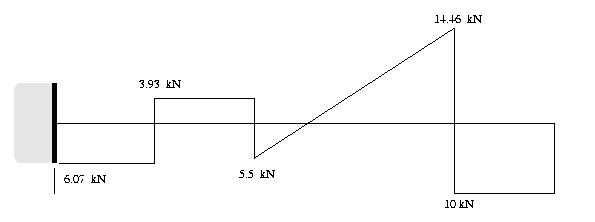
Figure 5 shows the distribution of shear forces.

Recall that the bending moment and shear force diagrams are related by:
                       dM (x)
       Shear force V = ------
                         dx
The change in the shear force at the supports corresponds to the vertical support reaction (details given below).
The reaction at each support corresponds to the sum of shear forces for the members attached to the support, minus the sum of the fixed end support forces.
The block of code:
   elmt1 = GetStress( [1], displ );
   elmt2 = GetStress( [2], displ );
   elmt3 = GetStress( [3], displ );

   print "\nSupport Reactions \n";
   print "===============================================\n";

   print "Support A : Vertical Reaction =", elmt1[1][4] - forces [1][2] (kN)  ,"\n";
   print "                  Wall Moment =", elmt1[1][5] - forces [1][3] (kN*m),"\n";

   print "\n";
   print "Support B : Vertical Reaction =", elmt1[2][4] - forces [1][5]
                                          + elmt2[1][4] - forces [2][2] (kN),"\n";
   print "\n";
   print "Support C : Vertical Reaction =", elmt2[2][4] - forces [2][5]
                                          + elmt3[1][4] - forces [3][2] (kN),"\n";
   print "===============================================\n";
retrieves the member forces for elements 1 through 3, and then systematically computes and prints the vertical reactions.
The program output is:
    Support Reactions
    ===============================================
    Support A : Vertical Reaction =     6.071 kN
                      Wall Moment =     16.07 kN.m

    Support B : Vertical Reaction =     9.464 kN

    Support C : Vertical Reaction =     24.46 kN
    ===============================================
Figure 6 shows the support reactions.

You should observe that the vertical reactions at supports "A", "B" and "C" sum to 40.0 kN, the total applied loading.