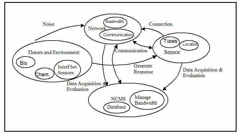
Figure 1. Schematic of System Framework and Boundary
Student: Rajeshree Varangaonkar
Faculty Advisors: John Baras and Mark Austin.
Date: September 2002 -- May 2003.
TABLE OF CONTENTS
Scope and Objectives
In the wake of recent attacks on buildings, security has become a major concern. The objective of the project is to conceptualize, design, and develop an intelligent sensor network for the security of any building. The link below gives an idea of its growing demand in the market
A brief concept is described below: The idea is to use sensors to track any untoward incident occurring inside and outside the building with a computer interface to detect any discrepancy recorded in the sensor measurements. The measurements will have to be sorted out to provide meaningful information. For this primarily required to classify data such that a sensor does not duplicate, contradict or give false information regarding an event or a measurement recorded by another sensor. A database must be provided to facilitate the interpretation of data provided by the sensors e.g. the acceptable signals of normal operation, signal values above the threat threshold. Next in line would be to consider integrating these sensors by a network to allow the information to be communicated to a central computer that will process data and generate alarms. The alarm system will also require a detailed analysis, its various aspects being local alert, remote alert, bad signals, emergency, sensor malfunctioning to cite some of its requirements.
Budget changes is a risk to be guarded against. Since the design is state of the art a shortage of funds can impair further development if costs have not been checked in the earlier stage of development
The project involves developing a smart sensor networks for smart buildings. The technical area splits in the following main divisions
The main topic presented below will be a part of the main system described above. It basically deals with the access at the entrance to the building. The idea is to prevent unauthorized access to the building and also to keep track of the people within the building. To ensure a secure access system a card reader with an integrated scanner will compare the biometric obtained from the system with the one obtained from the employee. This will be used to identify the card bearer.
System Framework and Boundary
Insert description .....
Figure 1. Schematic of System Framework and Boundary
Goals and Scenarios
Goal 1. System must allow user to easily program the settings
Goal 2. System allows easy enrollment of employees
Goal 3. Authorized Personnel must be allowed to gain access to the protected area
Goal 4. System must not allow unauthorized person in
Goal 5. System must track movement within building
Goal 6. A Visitor should be allowed to enter the protected area
Goal 7. In case of unauthorized access system blocks exits
Actors
1.	Authorized Personnel
2.	Unauthorized Personnel
3.	Card reader
4.	Control Room Staff
5.	Visitor
6.	Security
Use Case Diagram
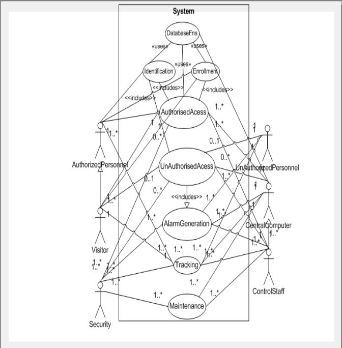
Figure 2. Use Case Diagram
Use Case 1. Authorized Access
Use Case 2. Un Authorized Access
Use Case 3. Tracking
Use Case 4. Alarm Generation
Use Case 5. Maintenance
Activity Diagram
Use Cases 1, 2, 3, 4 can be combined into one single activity diagram
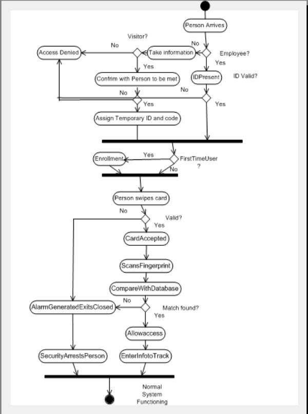
Figure 3. Combined Activity Diagram for Use Case 1 through 4
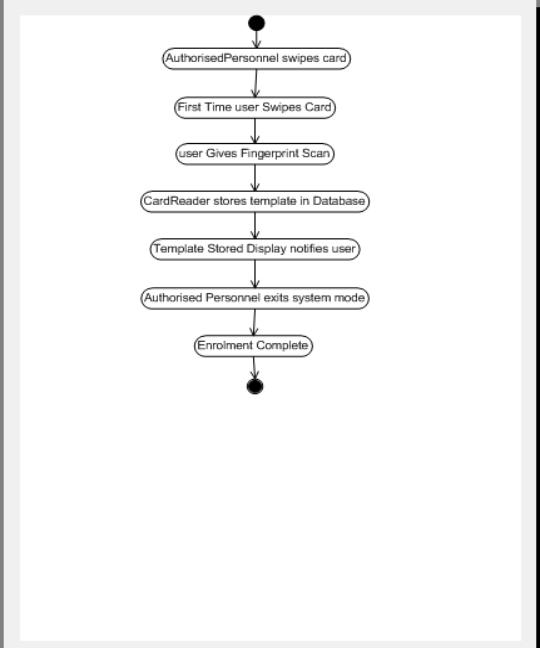
Figure 4. Activity Diagram for Use Case 5
Activity Diagram #2
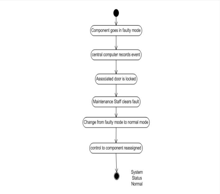
Figure 5. image010.jpg
Now that the baseline textual use cases and the scenarios are in place, we can now generate the requirements for the security identification system. Requirements are derived from various goals and scenarios, use cases so it is important to trace back the source of requirement.
High-Level Requirements
The high-level requirements for system access control are as follows:
| |
|
| |
System should prevent unauthorized access into the premises of the building |
| |
System should allow visitors inside. Should maintain a record of visitors for future use. |
| |
System should use a biometric to confirm identity of person along with access code and identity cards. |
| |
System should be tamper proof and should give a visual indication along with an alarm to indicate tampering. |
| |
System should be environment resistant. |
| |
System should be easy to maintain and install. |
| |
System should be able to communicate with the Network Management and control system |
| |
System should have enough capacity to store biometrics locally without increasing storage burden on the central computer. |
| |
System should prompt user to provide information and display error messages to user when wrong data is entered. |
| |
System should be highly accurate and reliable. |
| |
System should track an employee in the building. |
Table 1. Preliminary High-Level Requirements
Preliminary Assessment
These requirements are ambiguous and are not properly quantified. This is typically the case at the beginning of design and these requirements are typically expressed with words like should, may etc. So the requirements are basically expressed in English without any proper quantification. We break down these requirements to arrive at requirements mapping to the system, subcomponent and component levels. This is a top down approach. These lower level requirements should trace up to one or more higher level requirements. If it doesn't then it probably is not required. If a higher level requirement doesn't break down to a lower level requirement the requirement is nto being satisfied by the system design being considered. Similarly every requirement should trace to a component in the system.
Synthesis of Detailed Requirements
The requirements synthesis is as follows:
| |
|
| |
The building should be protected from unauthorized access. |
| |
Every employee will be equipped with an identification card to gain access to the building. |
| |
The card size shall be 2 1/8'' by 3 3/8'' (standard credit card size). |
| |
The identification card will be equipped with an identification number that will indicate that the card belongs to the company. |
| |
It shall be impossible to change or erase the information contained in the card by exposing the card to an electro-magnetic field of any kind, or physically alter the code without destroying the card. |
| |
The employee will start the access process by swiping the card in the reader |
| |
The reader will be wall mounted and of dimensions 7 X 4 X 3 and weigh < 5 pounds |
| |
It should be possible to program the reader. Programming shall be accomplished by means of an integrated 12 key keypad and 16-character LCD display. Employee will key in the access code with the help of the keyboard on the reader. |
| |
The Card Reader/Memory unit shall be immune to weather, moisture and any environmental hazards. It should typically withstand extreme temperature conditions and moisture levels. |
| |
Process of Enrollment (Defined as capturing biometric and information of a new user) should take < 40 seconds |
| |
It shall be housed in a structure of high impact material for complete protection against weather or tampering. |
| |
It shall be possible to place the associated electronics in a protected location preventing exposure of sensitive components to the elements and preventing tampering or vandalism. |
| |
During a power failure, the memory unit shall maintain its memory content for a minimum of 72 hours. Restart after power restoration shall be automatic. Reliability should be > 0.95 |
| |
Card will be equipped with a biometric template to indicate person belongs to company. |
| |
The card will have to be put in a card reader. The card reader will identify the card identification number by comparing with an inbuilt database. |
| |
The reader database should have a capacity to store at least 800 biometric templates and should have an expandable memory |
| |
System verification should be completed in < 25 seconds |
| |
The reader will be equipped with the Door Controls, Tamper Switch and should be able to Lock exits. |
| |
System will prevent tailgating or piggybacking. |
| |
The card reader with an integrated scanner will capture a biometric from the person and compare it with the existing template on the card and in the database. |
| |
An alarm will be generated alerting security and the exit near the access area is blocked if unauthorized the person fails the identification. |
| |
The system must be cost effective. Budget for employee identification is restricted to $5000. |
| |
When inside the building a person will be tracked with the aid of his identification tag when he gains access at any door. |
Use-Case/Task Interaction Matrices
Insert material from ENSE 621 .....
Traceability
Insert material from ENSE 621 .....
System Structure

Figure 6. Class hierarchy for System Structure
Statechart Diagram
Figure 7. Statechart for Intruder Behavior
Sequence Diagram
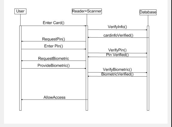
Figure 8. Sequence diagram for Swiping an Access Card and Verifying Access
Total verification < 5 second t < 15 secs
We create the system design by mapping chunks of system behavior onto objects in the system structure.
Mapping between System behavior and System structure

Figure 9. Sequence diagram for Swiping an Access Card and Verifying Access
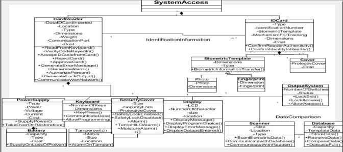
Figure 10. System Structure
Functions in Figure 9 are mapped to classes in the system structure.
Logical Design Of System
This section discusses the logical design of the Intelligent Network System. This logical design does not make any commitment to any kind of technology. Based on this logical design the physical design of the system is done.
Figure 11. High-Level Schematic for Logical Design
Requirements Traceability Matrix
| |
|
|
|
|
| |
The building should be protected from unauthorized access. | System access | ||
| |
Every employee will be equipped with an identification card to gain access in the building. | Card | Identification Number, Type |
|
| |
The card size shall be 2 1/8'' by 3 3/8'' (standard credit card size). | Card | Dimensions | |
| |
The identification card will be equipped with an identification number that will indicate that the card belongs to the company. | Card | Identification Number | |
| |
It shall be impossible to change or erase the information contained in the card by exposing the card to an electro-magnetic field of any kind, or physically alter the code without destroying the card. | Cover | Protective Cover | |
| |
The employee will start the access process by swiping the card in the reader. | Card, Card Reader | DataIDCardInserted |
AcceptCodeFromCard(), ConfirmReader- Authenticity(), Confirm- Identitytoreader() |
| |
The reader will be wall mounted and of dimensions 7 X 4 X 3 and weigh 5 pounds | Card Reader | Dimensions, Weight, Location, Type | |
| |
It should be possible to program the reader. Programming shall be accomplished by means of an integrated 12 key keypad and 16 character LCD display. Employee will key in the access code with the help of the keyboard on the reader. | Keyboard, Display |
NumberOfKeys, LCD |
KeyPress(), AllowProgramming(), DisplayDataasEntered(), DisplayProgramChoice(), DisplayMessage(), DisplayErrorMessage() |
| |
The Card Reader/Memory unit shall be immune to weather, moisture and any environmental hazards. It shall be housed in a structure of high impact material for complete protection against weather or tampering. | Card Reader, SecurityCover, Tamper Switch |
Protective Cover, Status |
AlarmOnTamper(), TempHiLoAlarm(), MoistureAlarm() |
| |
Process of enrollment (Defined as capturing biometric and information of a new user) should take < 15 seconds. | CardReader, Database, Card, Scanner, BiometricTemplate | DataIDCardInserted |
StoreData(), AcceptIDCode- fromCard(), BiometricInformation- Transfer() |
| |
During a power failure, the memory unit shall maintain its memory content for a minimum of 72 hours. Restart after power restoration shall be automatic. | Power Supply, Battery | Power, Voltage, Type, Capacity |
SupplyOnLossOfPower() TakeOverOnRestoration() |
| |
Card will be equipped with a biometric template to indicate person belongs to company. | Card, BiometricTemplate | Type, Dimensions | BiometricInformation- Transfer() |
| |
The card will have to be put in a card reader. The card reader will identify the card identification number by comparing with an inbuilt database. | Card Reader, Card | DataIDCardInserted |
ReadFromKeyboard(), AcceptIDCodefromCard(), RejectCard(), ApproveCard() |
| |
System identification should take < 1 seconds. | CardReader Database BiometricTemplate |
DataIDCardInserted, TemplateData |
BiometricInformation- Transfer(), CompareData(), |
| |
The reader will be equipped with the Door Controls, Tamper Switch and should be able to Lock exits. | CardReader,Output System, TamperSwitch | NumberOfSwitches, Status |
LockExit(), AllowAccess(), LockAccess(), AlarmOnTamer() |
| |
The reader database should have a capacity to store at least 800 biometric templates and should have an expandable memory. | Database | Capacity | StoreData(), DatabaseFull() |
| |
Reader will communicate with others on network. | CardReader | Communication port | Communication- WithNetwork() |
| |
System will prevent tailgating or piggybacking. | |||
| |
The card reader with an integrated scanner will capture a biometric from the person and compare it with the existing template on the card or after comparing with existing templates in a database. | CardReader, Scanner | Type |
ScanBiometricData(),
VerifyBiometrics(),
Communicate- WithReader() |
| |
An alarm will be generated alerting security and the exit near the access area is blocked if unauthorized person fails the identification. | CardReader, Output System, Number Of Switches, Status |
Generate- LockOutput(), GenerateAlarm(), LockExit(), LockAccess() |
|
| |
The system must be cost effective. Budget for employee identification is restricted to $5000 | CardReader, Power Supply, Battery, Cover, IDCard | Cost | |
| |
When inside the building a person will be tracked with the aid of his identification tag when he gains access at any door. | Card,CardReader, SystemAccess | Communication port, OpticForTracking |
In this section we transform the low-level requirements into qualitative specifications that can: (1) be evaluated via performance analysis, and (2) act as constraints in trade-off analysis.
Specifications
| |
|
|
| |
The total time to clear an employee | < lt 15 sec |
| |
The total time taken to enroll an employee | < 5 minutes |
| |
The total time taken to verify an employee. | < 5 seconds |
| |
The card size shall be | 2 1/8'' by 3 3/8'' |
| |
The capacity of the inbuilt database | > 800 templates |
| |
The weight of the system | < 5 pounds |
| |
Size of system | 7 X 4 X3 |
| |
Display features | 12 key keypad and 16 character LCD display. |
| |
Door controls | > 2 |
| |
Output ports | > 2 |
| |
Communication port | => 1 |
| |
Tamper switch | => 1 |
| |
Temperature resistance | -10 degrees to +60 degree Celsius |
| |
Security cover | Present with one backup |
| |
Battery | => 72 hours capacity |
| |
Minimum reliability* | 0.8 |
| |
Minimum number of readers | => 1 |
| |
Maximum reliability (note: reliability here is defined as the mean time between failures). | > 0.9 |
An intelligent sensor network for the protection of a building serves to protect the building from any untoward incident. It should thwart any possible threat to the system. Though the potential threats to such a system are numerous only one type of threat (Unauthorized access) has been considered here.
Measures of Effectiveness
The "measures of effectiveness" for such a system should include the system reliability and accuracy. It should also include the level of redundancy incorporated in the system to reduce potential danger due to a sub-system outage or malfunctioning. Since protection of system is the chief concern the cost analysis takes a lower priority in the analysis.
Performance Characteristics
Decision Variables
Problem Formulation
The cost is decided by:
Total Cost = R * (X1 D1 + X2 D2) + (Y1*DB1+Y2*DB2+K1*X1+K2*X2 + 25*4*W
where
R = number of card Readers
Reliability of card reader = Rcr Reliability of scanner= Rscan Reliability of card= Rcard Reliability of tamper proof covering= Rtap Reliability on adverse environmental conditions= Renv
Metric 1 � Cost(minimize) Total Cost =R* (X1D1+X2D2) + (Y1*$1+Y2*$2) +K1*X1+K2*X2+ 25$* 4* W where R= number of card Readers;
Metric 2� Reliability (maximize) Reliability= (Rcard)^( R*X)* (Rbattery)^(R*Yj)* (Rcomm)^(R*Kj) ?reliability is the product of independent component reliabilities. With Xi =Boolean variable giving manufacturer; i= 1,2 With Yj =Boolean variable giving manufacturer; j= 1,2 With Ki =Boolean variable giving manufacturer; i= 1,2
Metric 3- Minimize Time to clear one employee 0.5*(ca^2+cp^2) *(rho)^ ((sqrt (2*R+2)-1)) /(mu*(1-(rho))*R)< N1 Time
| |
|
|
| 600-700 | 75 | 0.020833333 |
| 700-800 | 80 | 0.022222222 |
| 800-900 | 64 | 0.017777778 |
| 900-100 | 14 | 0.003888889 |
| 1100-1200 | 15 | 0.004166667 |
| 1200-1300 | 48 | 0.013333333 |
| 1300-1400 | 65 | 0.018055556 |
| 1400-1500 | 45 | 0.0125 |
| 1500-1600 | 10 | 0.002777778 |
| 1600-1700 | 20 | 0.005555556 |
| 1700-1800 | 70 | 0.019444444 |
| 1800-1900 | 60 | 0.016666667 |
| 1900-2000 | 34 | 0.009444444 |
|
Mean = 46.1538462 Stdev = 25.09929 |
0.012820513 | |
| 0.006972025 | ||
Mean arrival rate= 0.012820513
The activity of the building at different times of the day is summed up in the table below:
Figure 12. Traffic Activity in Building throughout the Day.
Depending on the periods of the day there are times when the building is busy and others when it is not. We need to decide the average arrival rate to help us determine the number of readers to be installed to limit the waiting times for people.
Two major factors in the system:
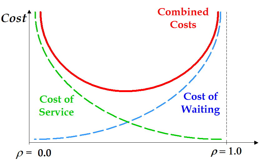
Figure 13. Tradeoff in Cost of Service versus Cost of Waiting
Characteristics of Queue Models
Key characteristics of the queue models are as follows:
Infinite population: leads to simpler model,
Finite population: arrival rate is affected by the number of employees already in
the system.
The number of employees that can be in the queue or under service. An infinite capacity means no customer will exit prematurely.
For infinite population, arrival process is defined by the inter-arrival times of successive customers. Arrivals can be scheduled or at random times.
Queue behavior describes how the customer behaves while in the queue waiting
�balking - leave when they see the line is too long
�renege - leave after being in the queue for too long
�jockey - move from one queue to another
�FIFO - first in first out (most common)
�FILO - first in last out (stack)
�SIRO - service in random order
�SPT - shortest processing time first
�PR - service based on priority
�random -- mainly modeled by using exponential distribution or truncated normal
distribution (truncate at 0).
�Constant
Service mechanisms describe how the servers are configured.
�Parallel - multiple servers are operating and take customer in from the same
queue.
�Serial - customers have to go through a series of servers before completion of
service
Combinations of parallel and serial are possible.
In mathematical terms, the queue characteristics are:
�l Customer arrival rate (in customers per time unit)
�m Service rate of one server (in service/transaction per time unit)
Performance metrics
�r Average utilization factor, percentage the server is busy.
�Lq Average length of queue
�L Average number of customers in the system
�Wq Average waiting time in queue
�W Average time spent in the system
�Pn Probability of n employees in the system
Utilization (fraction of time server is busy)= r=arrival rate/service rate
We assume that our system is G/G/k where G stands for a general distribution at arrival and Departure and k stands for number of servers.
G/G/k Assumptions
General inter-arrival time distribution with mean m and std. dev. = sa General service time distribution with mean m and std. dev. = sp Multiple servers (k) First-come-first-served (FCFS) Examples of distributions:
1.	Normal
2.	Weibull
3.	LogNormal
4.	Gamma
Coefficient of Variation C = stddev/mean
The average waiting times (approximate) are given by:
Waiting time increase with square of arrival or service time variation Decrease as the inverse of the number of server-service rate is defined as time taIn our case:ken for server to complete one transaction= 1sec in our case In our case the service rates provided by 2 manufacturers are 1 and 2.5 secs. If we assume that the total time taken to clear one employee is 15 secs including employee fumbling and blundering then it takes 15 secs for Manufacturer 1 to clear an employee and 17.5 seconds for manufacturer 2. In our case the utilization factor is 0.019
Solution Procedure
To find the optimal point in the design space, will be a tradeoff between the multiple criterion's that we are using for the design. Since the metrics are diverse with a conflict in queue time (which is to be minimized) and number of readers (which is to be minimized to reduce cost) the design point is a tradeoff between the 3 metrics. It is a solution that best satisfies all three criteria.
The objective function to be minimized is the Cost subject to the competing constraints of reliability and queue time. Increasing the number of readers reduces the queue waiting time; this strategy increases the cost and lowers the reliability. On the other hand, reducing the number of readers increases the queue waiting time; this strategy reduces cost and improves reliability. So a design point has to be found which satisfies all three criteria. The reliability of the system has to be increased and the queue times have to be decreased.
The optimization is done using Microsoft Excel solver.
Normalized Equations
Metric 1. Cost (minimize)
Total Cost = R*(X1*$1.2+X2*$1 + Y1*$1+Y2*$1.6 +K1*$0.5+K2*$0.3)+ $0.1*W
where R = number of card Readers;
Metric 2. Minimize Time to clear one employee
Time = 0.5*(ca^2+cp^2) *(rho)^ ((sqrt (2*R+2)-1)) /(mu*(1-(rho))*R) < k1 Time
Here, ca and cp are the coefficients for arrival and departure given as c= standard deviation / mean, rho is the average utilization factor, percentage the server is busy, mu is the service rate of one server (in service/transaction per time unit)
Metric 3. Reliability (maximize)
Reliability = (Rcard)^(R*Xi)*(Rbattery)^(R*Yj)*(Rcomm)^(R*Kl) < k2
This model assumes that reliability is the product of independent component reliabilities with:
Equations in EXCEL Format
Objective function
Min:
(1.2*B61+1*B62+B63+1.6*B64+0.5* B65+0.3*B66)*B17+0.1*C17��.Cost
Constraints
    0.5*(C16/C15)^2 *(C15/( 0.06667*B61+0.057143*B62))^ ((sqrt (2*B17+2)-1))
    /(H6*(1-(C15/( 0.06667*B61+0.057143*B62)))*B17)< N1 Time

    0.99^(B61*B17)* 0.95^(B62*B17)*0.998^(B17*B63)*0.98^(B17*B64)
    *0.9819^(B17*B65)*0.978^(B17*B66)> N2 Reliability

    0<= B61<= 1
    0<= B62<= 1
    0<= B63<= 1
    0<= B64<= 1
    0<= B65<= 1
    0<= B66<= 1

    B61= int	    ..Manufacturer1 for card+reader
    B62= int	    ..Manufacturer2 for card+reader
    B63= int	    ..Manufacturer1 for battery
    B64= int        ..Manufacturer2 for battery
    B65= int        ..Manufacturer1 for communication
    B66= int        ..Manufacturer2 for communication
    B17=>1          ..Number of Readers
    C17=>2          ..Number of engineers
    B17=int
    C17=int
    B61+B62=1
    B62+B63=1
    B64+B65=1
    B61*B65*B63+B62*B64*B66=1  ........Buy from the same manufacturer
Results
The following table gives the number of runs that were required to explore the design space and find the Pareto points. The constraints of time and reliability namely k1 and k2 were varied to find the cost (column: C), total time in system (W), queue waiting times (T) and Reliability (Re)
| |
( < Time & > Rel) |
|
|
|
|
|
|
| |
|
|
|
|
|
|
|
| |
|
|
|
|
|
|
|
| |
|
|
|
|
|
|
|
| |
|
|
|
|
|
|
|
| |
|
|
|
|
|
|
|
| |
|
|
|
|
|
|
|
| |
|
|
|
|
|
|
|
| |
|
|
|
|
|
|
|
| |
|
|
|
|
|
|
|
| |
|
|
|
|
|
|
|
| |
|
|
|
|
|
|
|
| |
|
|
|
|
|
|
|
| |
|
|
|
|
|
|
|
| |
|
|
|
|
|
|
|
| |
|
|
|
|
|
|
|
| |
|
|
|
|
|
|
|
| |
|
|
|
|
|
|
|
(**) Infeasible (since number of readers has to be an integer and the constraint is violated because the constraint values cannot be achieved). Possible solution points are 7 and 8
Analysis in Excel
Figure 14. Screendump of Excel linked to Optimization Module
Trade-Off Analysis Results
Cost versus Time

Figure 15. Tradeoff in Cost versus Time
Reliability versus Time
Figure 16. Tradeoff in Relability versus Time
Cost versus Reliability
Figure 17. Tradeoff in Cost versus Reliability
The Pareto point is 7. < 0.05 & > 90
Number of readers: R= 3; Cost= 8.3; Time= 0.039; Reliability= 0.91
This has been selected after deciding that this point gives the best results for all three objectives. Since reliability is an important criteria in access control system it is important to maintain reliability at least < 0.90. Also a system that doesn't give a reliability of 0.9 might incur additional losses in repair and downtime. The Cost has to be kept low, however for an identification system cost is not the most important criteria. Also the number of readers in a system should be such that the queue waiting times are within specifications.
System Test Plan
Insert material, Fall Semester 2003 .....
Insert references from ENSE 621 ....
Developed by Rajeshree Varangaonkar, Spring Semester 2003
Reformatted and slightly modified by Mark Austin, May 2003
Copyright © 2003, Rajeshree Varangaonkar,
John Baras and Mark Austin. All rights reserved.